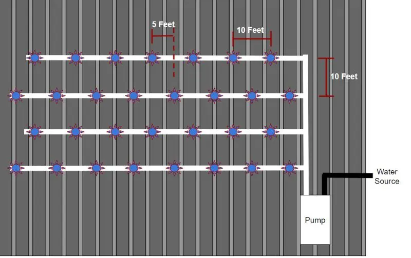
Diagram of Roof Cooling System

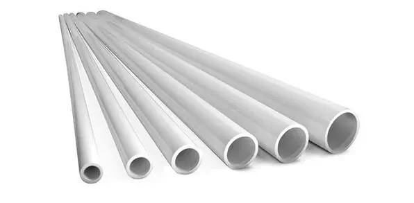
3/4 Inch PVC Required

Note: To complete the full connection of your run, you will need 3/4-inch PVC pipe.
To help save on shipping costs, we do not include this PVC pipe with your order. However, 3/4-inch PVC is readily available at most local hardware or home improvement stores. We recommend purchasing it locally for greater convenience and cost-efficiency.
Pump Installation
- Place the Roof cooler pump in its preferred location. Placing it on the roof near the system is preferable. If it cannot be placed on the roof, it is best to locate it as close to the input location of the roof cooling lines.
- Pump must be level.
- Water should be supplied to the pump inlet (black) a using 1-inch minimum source hose/pipe. Using smaller than a 1-inch supply can restrict the pump’s needed flow and damage the unit.
- Plug in the power cord to dedicated 20-amp 120 Volt receptacle. (Use GFCI)
- Priming is not necessary when a pressurized supply is available.
- Do not run the pump dry.
Output Installation
- Attach 1-inch PVC plumbing to output (white) of the pump.
- 1-inch piping is required between the pump and the output lines.
- Install the drain valve at the lowest point of the line as discussed in the design consultation for your system.
- Use the 1-inch to ¾-inch reducer (supplied) to transition from the 1-inch line to the output lines.
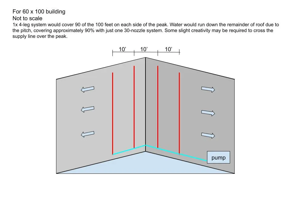
- Run the ¾-inch roof misting line parallel according to the design discussed in the planning stages of your system. Standard layout has lines spaced every 10 feet
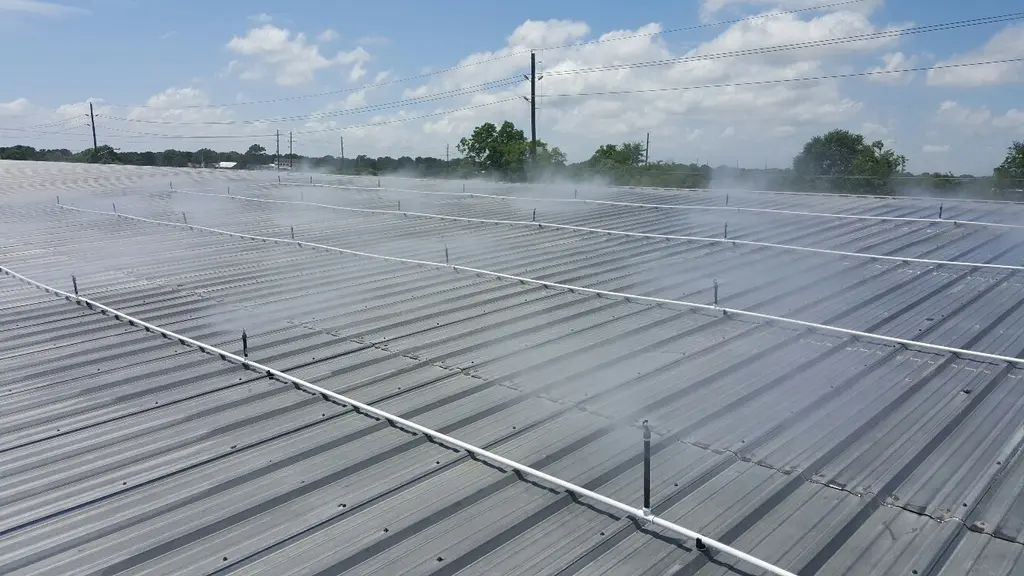
- For proper roof coverage, stagger the location of Roof misters at 5-foot intervals in relation to the parallel line. Each line should have roof misters spaced every 10 feet. (see picture below for an example).
- Secure roof misting lines with the magnetic clamps (provided).
- Ensure that adequate time is allowed for any PVC glues to dry before turning on the system.
Example

